And here’s the very first version, the 2-stage Amity amplifier, built on old Tektronix chassis by Matt Kamna in 1997:
300b lovers
I have been an owner of Don Sachs gear since he began, and he modified all my HK Citation gear before he came out with his own creations. I bought a Willsenton 300b integrated amp and was smitten with the sound of it, inexpensive as it is. Don told me that he was designing a 300b amp with the legendary Lynn Olson and lo and behold, I got one of his early pair of pre-production mono-blocks recently, driving Spatial Audio M5 Triode Masters.
Now with a week on the amp, I am eager to say that these 300b amps are simply sensational, creating a sound that brings the musicians right into my listening room with a palpable presence. They create the most open vidid presentation to the music -- they are neither warm nor cool, just uncannily true to the source of the music. They replace his excellent Kootai KT88 which I was dubious about being bettered by anything, but these amps are just outstanding. Don is nearing production of a successor to his highly regard DS2 preamp, which also will have a unique circuitry to mate with his 300b monos via XLR connections. Don explained the sonic benefits of this design and it went over my head, but clearly these designs are well though out.. my ears confirm it.
I have been an audiophile for nearly 50 years having had a boatload of electronics during that time, but I personally have never heard such a realistic presentation to my music as I am hearing with these 300b monos in my system. 300b tubes lend themselves to realistic music reproduction as my Willsenton 300b integrated amps informed me, but Don's 300b amps are in a entirely different realm. Of course, 300b amps favor efficient speakers so carefully component matching is paramount.
Don is working out a business arrangement to have his electronics built by an American audio firm so they will soon be more widely available to the public. Don will be attending the Seattle Audio Show in June in the Spatial Audio room where the speakers will be driven by his 300b monos and his preamp, with digital conversion with the outstanding Lampizator Pacific tube DAC. I will be there to hear what I expect to be an outstanding sonic presentation.
To allay any questions about the cost of Don's 300b mono, I do not have an answer.
| Post removed |
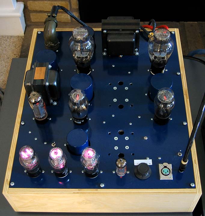
Here’s a close-up of the 2003 Karna amplifier, showing one channel of the audio chassis, with the power supply chassis out of sight. These have been my personal amplifiers until I received a pair of Statements about eight months ago. Note the aviation-grade Amphenol connector on the rear of the chassis. All connectors and cables are rated for 1.5 kilovolts, using transmitter-grade coax cables to carry the two separate B+ voltages to the audio chassis. In case you are wondering what all these tubes are doing, the input tube is a 5687 (or 7119), the drivers are old-stock 45’s, the outputs are 300B’s, one pair of VR150’s are for the drivers, and a single VR150 is for the input tube. The single EL34 is a current source that feeds the VR tubes. The four blue-painted cylinders emerging from the chassis are General Electric industrial motor-run capacitors. The Statements and Blackbirds are an update of this over-the-top project. I was doubtful the Karna could ever be manufactured until Don came along, with his lengthy experience making the Valhalla (KT66) and Kootenai (KT88) amplifiers. Not only is it more compact, the new Don Sachs power supplies are an order of magnitude better ... and they didn’t exist in 2003.
|
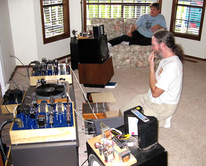
The Statements are the previous versions. I strongly urged Don to use a spacious layout, with all components on a single layer. Easier to build and signal-trace. Don ran with the suggestion and improved it by putting all the power supply components on the right side of the chassis, all the audio circuits on the left, with a shield between the two sections. The wiring for the audio section, in particular, is really simple ... transformers, tube sockets, cathode resistors, and bypass caps. The wire lengths for each half of the circuit are symmetric, while cathode resistors, bypass caps and local grounds go to turret boards next to the tube sockets. The bigger chassis also run cooler, as you might expect, since heat-emitting components are further apart, and the top plate is now 18" wide. The Blackbirds might look big, but they fit just fine on standard racks. Sonically, the Statements and the Blackbirds are pretty close. They are all descendants of the original Karna amps, which date back to 2003. Unlike the Karna amps, the Statements and Blackbirds are on two chassis instead of four, which vastly simplifies grounding. Here’s a picture of Gary Pimm (foreground) and Gary Dahl (background), taken in 2003. The Karna’s have the distinctive blue chassis, and the separate power supply chassis are behind the amplifiers. The AMT-1's are Gary Pimm's speakers.
|
Alexberger, the Cinemag input and interstage transformers are under the top plate. These are the third generation of the custom Cinemag transformers we started with. The two Monolith transformers are visible on the rear of the top plate. The other things under the top plate (right side) are the B+ and filament regulators, and the master soft-start circuit, with an external 12V trigger. The point-to-point and turret-board wiring under the audio side (left) is very simple, with only transformers, tube sockets, cathode resistors and bypass caps. No current sources or other gizmos. |
@alexberger Yes, but only at radio frequencies. No shielding at audio frequencies, and for that reason steel is likely a better choice if you're running single-ended. We use aluminum chassis in most of our stuff, but its balanced and so does not need shielding to be quiet. |
Hi @lynn_olson @atmasphere , Thank you for useful information. Does aluminum provides any shielding? I will use an aluminum chassis. There is a beautiful picture of Blackbirds. But I don't see inter-stage transformers. Are they under the hood?
|
@alexberger I can confirm everything @lynn_olson mentioned regarding your post in his above. Pay attention to all those issues! Regarding this question which has to do with grounding. You’ll want to ground your chassis if its metal (and if you’re running single-ended, ferrous materials will provide audio-frequency shielding). So the ground connection of the power cord should be tied to the chassis. The audio circuit, if tied directly to chassis, leaves you open to ground loops. To avoid this, lay out your amplifier circuit so all the points that go to ground do so to the power supply (star grounding is nice) without touching the chassis. Grid and cathode connections for each tube section (the ground side of the grid resistor and ground side of the cathode resistor) should be common and use a single wire going to the star ground. This forces noise imposed in that wire to be common mode and so will reduce noise. The spot in the power supply to which you tie your grounds can be a buss tying all the filter cap grounds together. Once you have all the grounds starred together, at that point you need to reference the chassis ground. That can be done several ways: you can use a simple resistor from the audio ground to chassis ground. You can use a pair of rectifiers in parallel, each opposite of the other, with a resistor in parallel with that. This higher impedance is presented to ground currents between chassis and the audio grounds which otherwise set up the ground loop. Be sure to have the input connectors also isolated from ground. Most RCA connectors are supplied with shoulder washers for this purpose. In this way, the chassis can be a relatively quiet shield for the audio circuit. You’ll find the audio circuit to be quieter with this practice. |
| Post removed |
| Post removed |
| Post removed |
1. If the heater windings are not shielded from the high-voltage B+ windings, switch noise from the B+ section can be capacitively coupled to the low-voltage heater windings. Although indirectly heated tubes have significant isolation from line noise, it is not 100%, so some of that switch-buzz gets through. If you listen closely, you will probably hear it. There are several solutions: A) get a power transformer with electrostatic shielding (copper foil) between HV and LV sections B) go to DC heating with a regulator C) use a separate heater transformer. When none of these are done, yeah, that’s cost-cutting, no matter how fancy the name brand. If swapping the rectifier tubes makes a notable difference in the sound of the amp, there’s something wrong, or not optimal, with the power supply design. 2. Yes, the two grounds must connect together at one point, and only one point, preferably the chassis. There’s an old joke: when two engineers get together, they will come up with three grounding solutions, and all of them will be right. Grounds (and shields) should never float, ever. That’s bad practice and a possible safety hazard. Determining the best connection for the ground or shield usually takes a bit of thought (which is why it’s called engineering). There are whole books on grounding. It is not a trivial subject. Part of the problem is language, because one word covers several things: A) Safety ground B) Current return path for the DC currents that power the tubes or transistors C) Current return path for the AC audio signals going through the circuit D) RF and noise shielding |
Hi @lynn_olson , I have a couple of technical questions: 1. Is it a good idea to feed indirect heated tubes AC filament with a separate dedicated power transformer? In my integrated SET 300B amp input tubes receive relatively low level signal after the input potentiometer. 2. I use interstage transformers and separate PS for driver and input tubes. As a result, I have two separate GNDs: 1st - for output circuit and PS 2nd - for input/driver circuit and PS. Should I connect both these GND together to the amplifier chassis at one point? Or can I leave one of these GND floating? |
Here’s the latest: Don is training the folks in Salt Lake City as we near production. The Raven preamp is the same preamp you heard at the show, while the Blackbird now has KT88 drivers, at twice the power of the 6V6 drivers, with third-generation Cinemag interstage transformers and Monolith output transformers, If you’re wondering who Monolith is, you heard them in the Songer room on the Whammerdyne amplifier. Merry Christmas, Happy Hannukah, and a Happy New Year, to all! |
@jaytor Sure! We are assuming that you plan to use a high efficiency speaker so you’re not also looking for a lot of gain. But I have to get some clarification- do you want the ability to have enough drive for the power tube, along with enough voltage gain at the same time? They are not always the same. Tubes that can swing the voltage needed for the 300b include the 12AT7, 12AU7, 6CG7, 6SN7 and so on. I would stay away from the 6DJ8 and similar frame grid tubes; while they are very linear and can handle the current you need, they aren’t very good with microphonics as they are not meant for audio. A bipolar supply supply is helpful because there is always a bit of differential performance left on the table by any CCS. The more negative the supply, the higher the impedance of the CCS can be (which is a good thing). You can, with modern semiconductors, easily built a good CCS that will work on -100V, but If you are already building a B+ supply, its really not all that hard to build a B- supply from the same transformer. I like to use a separate power transformer for the driver and voltage amplifier, so as to minimize noise appearing in the power supply of the output section from messing with the rest of the amplifier. This helps reduce IMD.
|
@charles1dad - Thank you. @atmasphere - One of the reasons I was thinking of using single section tubes was to improve matching. I've noticed this section matching problem in LTPs I've been playing with, particularly with some of the soviet tubes (e.g. 6N6Ps) where the quality control seems to be lacking. Are there any tubes that, in a PP IT loaded design, would be reasonably linear and provide enough drive for a single 300B without a cathode follower stage? I'm confused why a bipolar supply would help. I'm assuming I'd need to have some kind of negative supply for the fixed bias circuit which I would also use for the LTP CCS connection, but I would expect this to be around negative 100V. Alternatively, I could use a balanced input transformer with the secondary center-tap tied to a positive voltage to allow enough voltage across the CCS tied to ground. |
@jaytor You’ll want as much gain out of the voltage amplifier as you can get, since the more gain also yields better Common Mode Rejection Ratio. But you’ll need a good Constant Current Source to optimize the gain stage. The D3A, triode strapped, will give you a good mu value to work with, although you could get that with a single 12AT7 and be in the same ballpark. A 12AT7 will allow for plenty of bandwidth. If you use a driver transformer as a plate load, the issue you’ll be up against is imbalance of plate current between the tube sections. The better your CCS the less you’ll have this problem, and matching is a very good idea. The more current that isn’t cancelled in the magnetic core you can also expect greater distortion. So you can see getting the plates to have equal plate voltage is important. To this end, using a balance pot in the cathode circuit to balance the plate currents, while effective, has the effect of also reducing the differential effect, increasing distortion and reducing gain and bandwidth. So matched tube sections and a really effective CCS are paramount. One thing to consider is its really impossible to get a perfect center tap in a transformer. Its always going to be a little off. Since its often difficult to get really well matched tube sections (they should be matched on a curve tracer for best results), I prefer to use RC coupling to a cathode follower, which is in turn direct coupled to the grid of the power tube. The power tube would thus obtain bias from the driver tube. If the driver tube gets weak, the power tube will conduct less also, preventing damage. I explained this topology earlier in this thread. If you are considering using a differential amplifier as the input voltage amplifier, you really should consider a bi-polar power supply of equal B+ and B-. This will improve the differential effect and the effectiveness of the CCS. If you have such a power supply then you have a good way of setting up that cathode follower I mentioned. If you go this route, care must be taken to make sure the plate of the driver tube is well bypassed so even at full output there is no noise, no artifact caused by the signal on that plate. This will really help the amp assume greater authority. |
@lynn_olson - what are your thoughts on using a balanced input stage to drive a single ended 300B? My front end hardware is all balanced and I like using balanced connections. I’m thinking an LTP with a CCS on the cathodes and a push/pull interstage on the anodes. Output of the IT driving a single 300B with fixed bias connected to the other side of the IT secondary. I haven’t decided which tubes to use for the input stage, but was thinking about triode strapped D3As. I have a nice pair of Monolith Magnetics SX-11 output transformers that I want to use. |
The tricky bit using regulators is bandwidth. The output of any regulator has a certain impedance. What you are looking for is a linear impedance curve across the entire audio band. The tube regulators often had a problem with this; the output impedance rises when the regulator meets its bandwidth limit. At this frequency the regulator has to be bypassed with a capacitor that keeps the output impedance as linear as possible. It won’t be perfect- usually you wind up with a step in the output impedance at the crossover point. Too much capacitance can cause the regulator to run hotter and with tubes, you can have reliability problems that might occur when the capacitance is charged during warmup. Solid state regulators often have much wider bandwidth so don’t usually need so much bypassing, but they can have stability problems so are often bypassed with a small capacitance at the output to prevent it oscillating. Adding additional capacitance to the output of the regulator will do little to improve sound quality and if enough capacitance is added, will increase the heat of the regulator and could threaten its reliability. If the regulator is properly bypassed and operated well within its limits then they will tend to be neutral. To help the regulator along, its a good idea to do as much as you can to minimize noise at the input of the regulator. For example a PI network is helpful to reduce the amplitude of the sawtooth waveform at the regulator’s input; this will reduce the work the regulator has to do, which can reduce its operating temperature. |
The sonics of power supplies are different for SE and PP amplifiers, so it is impossible to generalize without specifying the amplifier topology. The modulations of supply current on the main B+ supply in a single-ended amplifier are simply the music itself, with an addition of noise from the rectifier stack. Single-ended amplifiers are entirely Class A in operation, by the way. This is not true for a balanced or push-pull Class A amplifier. The modulation of music on the supply is reduced by 30 to 35 dB (depending on balance), and what’s there is doubled in frequency, similar to a balanced-detector in a radio. The balanced-detector artifacts are the result of symmetric nonlinearities in the balanced pair ... if they have 100% distortion, you get a balanced detector. If the balanced-pair distortion is a small fraction of that, say, 1% or less, then you still get balanced-detector distortion but much reduced in level. If the balanced-pair are 100% distortionless, then current draw is constant, with no variation. But distortionless balanced pairs exist only in fantasy, so there is always some variation in current draw with real circuits. In a Class AB amplifier, it is worse, with three regimes ... Class A at low levels, and clipped-off Class B at higher levels. This has an impact on the sonics of the supply. A single-ended amp is simple ... improve the musicality of the supply, since music is directly impressed on it. Push-pull is more difficult ... the modulations on the supply are a mix of residual imbalance and balanced-detector artifacts, and significantly worse if Class AB artifacts appear in the output stage. This is the strongest argument for stage-to-stage isolation, so distortion artifacts from a high-level stage do not modulate a lower level stage, In the Raven and Blackbird, we go the additional mile by having a shunt regulator for the input section. The shunt regulator operates by having a current draw that is the precise inverse of the audio-circuit fluctuations, so the net current draw is constant. By contrast, in a generic Dynaco or Mullard circuit, we have several topologies, with only simple RC power-supply filtering between stages. The output stage is typically Class AB semi-pentode, the driver is Class A triode, and the input is single-ended triode. All three have different distortion signatures. |
It turned out the ultrapath capacitor wasn’t sonically that different than a conventional cathode bypass cap. In the context of a regulated supply with an output impedance of 3 milliohms, and equivalent to a 2000uF passive supply, the Zout of the power supply is effectively zero compared to the cathode bypass or ultrapath capacitor. By comparison, a passive CLC supply with a Zout similar to a 100uF capacitor, a ultrapath bypass might be more appropriate, but then the exact value has to trimmed against the noise introduced by the passive CLC supply. By contrast, the active regulator has 130 dB of noise isolation, so there are no issues of noise introduced by the supply and getting into the cathode circuit. So it all comes down to the power supply. The optimal solution for a passive CLC supply, with its distinctive noise profile, might not be optimal for an ultra quiet supply with a very low output impedance. And then we get into the deeper waters of the sonics of the regulators themselves. Some are slow and noisy, and intermodulate with the music. Others are fast and silent. Regulators do not all sound the same, and passive CLC supplies can have a signature too, depending on the capacitors chosen. There is no one-size-fits-all solution. I should mention the battle of active vs passive supplies has been going on for at least three decades, and is somewhat biased by prejudice against the low-quality active regulators available 30 years ago. High-voltage regulators now are far better, and far more reliable, than what we had then. |
@alexberger Here's something to keep in mind. If you are not using feedback, then its likely at either end of the bandwidth of the amp that the FR will fall off on a 6dB slope. Filter theory tells us that a 6dB slope introduces phase shift to 10x or 1/10th the cutoff frequency. So a 20Hz cutoff will manifest phase shift to 200Hz since there is no feedback correction. The ear perceives phase shift of a single frequency very poorly, but over a band of frequencies it interprets it as tonality. At high frequencies the ear also uses phase to sense the sound stage. A high frequency rolloff above the audio band can cause darkness in the presentation. At low frequencies a rolloff will be perceived as a loss of impact. Transformers have bandwidth limits. The smaller you make the transformer, the wider its limits can be. So you have a chance using an interstage transformer to have one that has good LF response- 5Hz is a good place to be. Because you are designing an SET you're dealing with a low frequency bandwidth issue in the output already. All I'm saying here is the less phase shift you present to the output section, the less phase shift will be present in the output. If you're planning to use a sub with this system this might not be much of a concern. But of you really want to use a sub properly, it should be cut off no higher than about 80Hz otherwise it will tend to draw attention to itself, requiring that it be in the same place as the main speakers. If a sub is used, probably best to drive it with a preamp signal rather than that of the amp due to this bandwidth issue.
|
Hi @atmasphere , The bottom end is predictable. ~8K 6sn7 (260v, 9mA) internal impedance and 70-80H transformer primary inductance gives -3db around 20Hz. Actually I measured -2.37dB at 20Hz and -3.62 at 15Hz. |
You can also see that bandwidth has opened up a bit. Something to keep in mind: when you load down that interstage transformer, it changes the load presented to the tube driving it. You might be able to further optimize the circuit by making changes in the driver tube circuit. Also, if I were you I'd be try to sort out why the FR drops off so dramatically at the bottom end (is it the transformer or something else). |
| Post removed |
I continued tuning my amplifier for the Hashimoto A-107 interstage transformer (IT). I changed the load resistor from 57K to 39K Ohm. The difference in square wave overshoot is very small, but frequency response peak is just +0.5dB instead of +1.3dB. https://photos.app.goo.gl/tdDuNM15cziP4o5g9 But the most important - the rough upper mid coloration was gone with 39K. I also increased 6sn7 idle current from 7.5mA and 9mA. When it was RC coupling before the idle current was 6.2mA. In general, sound became more refined and organic with much better low level details. Now in addition to advantages that IT gives versus RC that I talked about before (like faster transients, better more detailed rhythm reproduction and bass control). I got more low level details, much more realistic drums kick/punch reproduction, piano is more real, as well as timbales, better instrument separation (less congestion on complex music), and more real musicians presentation in my room. Next step moving from an old amplifier box + power supply external maquette to two box solution (stereo amplifier + power supply). |
To complete the current loop around the 300B (or any other power tube), there has to be a low-impedance path from the cathode to the ground side of the filter cap of the B+ supply. This can be (A) fixed-bias operation with the cathode at ground, or using something like a 10-ohm current-sense resistor. This requires an adjustable low-noise -80 volt supply, and a meter across the current-sense resistor. Adjust the minus supply until you have 70 to 80 mA flowing through the 300B. The plate voltage also has to be reduced by 80 volts or so, since you’re not dropping 80 volts across a cathode resistor. A potential source of instability for the fixed-bias circuit is having a regulated minus supply while the main B+ supply is unregulated. Small variations in AC power voltage can result in large changes in bias point. The solution is either have a tracking feature for the minus supply, or regulate the main B+ supply, which is not cheap. In other words, when both ends of the tube are controlled by plus and minus supplies, they should track each other, or be fully regulated. The (B), self-bias option is dropping 80 volts across a 20-watt cathode resistor, and bypassing it with 200 uF of film capacitor. B+ will be around 425 to 480 volts at the top of the output transformer primary. Sonics will be strongly affected by the quality of the film capacitor since it is in the main current loop of the 300B. Adjustment of current flow is not necessary since the cathode resistor provides a degree of negative feedback for the DC current flow through the tube. |
Hi @lynn_olson @atmasphere , Thank you a lot for detailed answers! I have another question: In balanced push-pull self bias output tubes is not a big issue because the cathode resistor and capacitor are out of the main signal path. But what to do in my case with a 300B SET. Now I use self bias with 50uF AN Kaisei NP bypassed by 4750uF Nichicon and two Ohmite Gold 10W resistors in parallel. So the question is what is the best solution for SET? Fixed bias? Is fixed-bias reliable and safe? What is important to know for building a negative power supply for fixed bias? |
Full wave is preferred if you are planning a bipolar (+ and -) power supply. If only a single pole, a bridge does have the advantage of the power transformer not needing a center tap. That advantage is because a center tap is never truly centered, so the output from the transformer applied to a full wave is slightly different with each half of the AC waveform. This means the diodes are making slightly different current spikes as they commutate (turn on and off). That might not make much of a difference, since the best way to snub the circuit (to kill the swept resonance that occurs when the diodes shut off) is to snub the rectifier with a resistor and capacitor in series across the input to the diodes. In case its not clear, the source of 'diode noise' is really the power transformer inductance, interacting with the capacitance in the junctions of the diodes. For this reason, if you use a semiconductor rectifier setup, you really want to keep the leads from the power transformer as short as possible. If you do that right, you can make the nasty silicon rectifiers perfectly silent; obviating any need for a tube rectifier (who's main advantage is low 'rectifier noise'). I put that last bit in quotes since the transformer is what is causing the noise, reacting to the rectifier. In the old days it was common practice to put a 0.01uf cap in parallel with semiconductor rectifiers. This does nothing and might actually make the problem worse. Any diode junction, if you plan to snub the rectifier itself, must use a resistor in series with a small capacitance to properly snub the rectifier. But usually you can have great success with just a resistor and small capacitance at the input to the rectifiers instead, since snubbing the transformer is putting out the match rather than the forest fire. |
They’re different. * Full-wave uses two rectifiers and only one half of the secondary at a time. Each active half-secondary switches back and forth 120 or 100 times a second. * A bridge uses four rectifiers and the entire secondary all the time. The current through the full secondary switches direction 120 or 100 times a second. That’s the most basic level. To a first approximation, full-wave transformers need twice the voltage for the full secondary, since only half the winding is used at a time. In more depth, if there is a first cap following the rectifier(s), the rectifiers only conduct for very brief intervals (a few milliseconds) when the cap recharges. These brief, high-current pulses can shock-excite the half-secondary, causing ringing from the abrupt cutoff of the unused half-secondary. The shape of that shock is controlled by the on-off ramp of the diode, and if there are charge-storage effects from a solid-state diode. The rest of the time, after the first cap is recharged, the diodes are switched off, and the amplifier is powered from the charge in the first capacitor. This cap is steadily discharged until the next pulse comes along and recharges the cap all over again. This charge-discharge cycle happens 120 or 100 times a second. There's a tradeoff in sizing that first capacitor. If you double the size, the voltage sags half as much ... but the inrush current is also doubled, too. If you really overdo it, the inrush current will be so large it pulls the circuit breaker. A "choke-fed" supply has the diodes directly feed a special inductor rated for very high voltages. The diodes remain "on" for most of the AC waveform. But ... the special inductor has to tolerate a significant voltage kickback when the diodes do cut off ... this in turn can create ringing and possible voltage breakdown of the windings in the choke. All of these supplies create very large current pulses that radiate into the air and are are transmitted back down the power cord of the amplifier, which turns the cord into an antenna radiating a 120 or 100 Hz pulse train, with harmonics extending throughout the audio band, A general rule-of-thumb in power supply design is to minimize the "loop area" of the most powerful transmitters, which are the loop created by the transformer secondary, the diode array, and the first filter element. Minimizing the wire length, tightly twisting these wires, and keeping them as far away from the input circuit as possible is highly desirable. This is why running AC power to a front-panel switch is undesirable from a noise perspective. There’s a simple emulator called PSUD that lets you play with different power supply topologies and circuit values, and lets you scale the load to a real amplifier. |
I ask again this technical question again. Which rectifier is better: full wave or bridge? My driver stage power transformer has three taps: 250 0 250 and supports both - full wave and bridge. Full wave affords use x2 times bigger DC current. Why do many people prefer a bridge rectifier over full wave? |
The gear could easily be wired for 220-240 VAC 50Hz. Everything we use supports it except for ordering multiple primaries on the power transformers. Again, the project must get off the ground in the USA/Canada. If they are selling, and people from Europe are inquiring, then perhaps Spatial may be interested in that market. Hard to say. If demand is outstripping supply there is no reason to make your life difficult dealing with markets outside N America. Down the road......maybe |
@donsachs That is why its worth it to work out the math. The lead content in your product is a percentage allowable. Since you have a lot of transformer weight and otherwise the circuit is fairly simple, my surmise is you can use leaded solder with no worries. But you'll want to look at the regulations and do the math to know for sure. |
I'm not sure what to tell potential overseas customers to do. Sure, after you hear all the market buzz and read the first reviews, you might be tempted to get on a plane, fly right to Salt Lake City in the state of Utah and buy yourself three good-sized boxes ... a matching Raven, and a pair of brand-new, state-of-the-art Blackbirds. Be the first person in London or Berlin to own the full set. How cool is that? But ... if anything goes wrong, or you just want some hand-holding, or want to ask what our favorites cables are ... you're kind of on your own. You're not in the same time zone as we are. We don't know anything about the ins and outs of UK and European power supplies, nor what favorite NOS tubes are in your area. Sure, with time, we'll find European affiliates that are a good match. With time, in Asia as well. |
Which is why medium to large scale companies have regional service centers, which combine repair, refurbishing, and overall product support in one center. It’s equivalent to a low-yield manufacturing center with a marketing wing (in the local language) attached. They support local retailers, or have direct customer support, and offer the kind of services manufacturers do, just on a smaller scale. Somebody to answer the phone. A parts warehouse. Several techs to repair or upgrade the product. Somebody to manage the facility and make sure things actually get done, along with inventory and personnel management. In short, at least three to ten people working full-time, along with leased space in an industrial park. It’s equivalent to a small factory, with equivalent monthly overhead costs, too. Once your company passes the threshold of about five to fifty million dollars a year in sales, yes, opening overseas centers in regional markets makes economic sense. You can afford to hire three to ten new workers on another continent, and train them and point them in the right direction. Opening a regional service center requires a pretty steep investment in time and money. Otherwise, you are supporting the overseas customers by remote control, with very expensive shipments back and forth, and a certain percentage of those returned products severely damaged in shipment because the customer threw away the original packaging and improvised their own packaging. |
I have a thorough dislike of working with lead-free solder. Nothing flows in a point to point build like a good 2% silver solder. Lately I have been using Wonder Solder for the past year or two and it is just wonderful to work with. Of course, one could use lead-free solder, and pass all the hurdles and build things for shipping in large numbers to the EU. First you get the product off the ground in N. America. We have pretty much free-trade between Canada and the USA, and it is quite easy to make things in either country and ship to the other, duty and tariff-free. My main point above was that it is very expensive to deal with customer support across the pond. If you ship 100 things to 100 people, about 1% of the time something happens. For example, UPS will admit that they have a 4% claims rate. Things happen. No matter how robust you make something, and how thoroughly you test it and the tube set before you ship it, things happen a very small percentage of the time. Or a customer plugs a tube you didn't sell them in there and it grid shorts. This gear is quite robust against serious damage when that happens because in all these years of building things, I have seen all sorts of failures. When a bad tube kills something, I improve designs so that will only blow a fuse instead next time. So these things are quite stable, but still, every now and then things happen. When they happen in N. America it is far cheaper to sort out. You always take care of the customer. It is much more expensive to do so overseas..... |
Yeah, RoHS-approved solder might be a stumbling block, since it requires higher temperatures and a little different technique. We’ll cross that bridge when we get there. Our first goal is getting production under way in Salt Lake City, home of Spatial Audio. Fortunately, both Salt Lake and Denver have a number of aerospace vendors that make various subassemblies for rockets and satellites. |
Japan has a very good used audio stuff market with Tango, Tamura transformer; Kondo, Acrolink cables; used amplifiers and CD player,... Japanese people sell all this stuff on the internal market. A very few used stuff from Japan is sold internationally , for example, on eBay. And because Japanese people don’t use eBay, all used Japanese audio equipment sold by hucksters - prices on eBay are at least twice higher than in the local market. |
To gain the CE mark (which says that the product meets EU Directives) you can self-certify and no lawyers needed. Its not intended as a trade barrier. If there are no digital or switching circuits involved, you have exemption from a good number of directives. Beyond that, if good practice for the AC wiring is observed (with a proper AC ground if a metal chassis is employed) and there are no exposed voltages, then you are 95% of the way there. It isn't required that you have a tube cage but if its not shipped with the equipment it must be available as an option. Finally the CE mark must appear somewhere: either on the shipping box, the associated owner's manual or the equipment itself. Its a good idea to test the equipment for RFI generation, even if there are no RF sources such as switching technology. If you paid attention to Ps and Qs regarding layout and grid stoppers this is likely not an issue. RoHS must also be observed. For the most part this means lead free solder, but there's a percentage involved so it is possible to use leaded solder. You'll have to review the regulations on that. |
I wonder how these Japanese engineers/designers view the products manufactured by Robert Koch (Robert Koda Audio). His approach seems to be a blend of Japanese aesthetic/philosophy and heirloom visual appeal for the North American and European markets. I don’t know how well received his components are in Japan. Charles |
As Whitestix mentions above, the Japanese have a "purist" esthetic that applies to audio. But it goes much deeper than that. The CEOs and top engineers of Japanese, Korean, Taiwanese, or Chinese companies are not going to be impressed by the latest mass-produced gadget. Hardly. That’s the stuff they make every day, and they make it to very high reliability standards. What they appreciate is artisan audio made to the highest standards, by artisans of superb taste. Not 1" thick anodized-aluminum front panels with a giant meter in the middle. That only impresses naive Americans who have never worked in manufacturing, What impresses them is genuine American aerospace-grade quality, if circuit boards are involved, or artisan hand-tuned point-to-point circuitry. And they are not impressed by magazine reviewers, since they have an insider’s view of the publishing industry, and are very aware of how American marketing works. |
I was only 11 at the time, but I was dazzled by the private tour of Kurobe Dam. It’s size of Hoover Dam and freaking huge. The dam was nearly finished when we visited as guests of Kansai Electric, and we took this strange little Elves railway deep, deep into the mountain. We got out of our mini-train carriage into a brightly lit station with gleaming tiles, and directly opening into a modernist office area, with desks and office furniture. Rather than office windows looking outside, there was a massive expanse of glass overlooking the turbine hall, from three stories up. I assume the control room was in the floor underneath us ... didn’t get to see that, but we did go to the main turbine hall. Two were up and running, the third Hitachi-made unit was on a crane, and there was a vast and deep concrete pit for #4, yet to arrive. All new and the walls all done in gleaming white tile, not bare concrete. Basically, an office and power station deep in a mountain, with a very quiet thrum as enormous quantities of water flowed through the penstocks into the turbines. You could just barely feel it. We left by another route and saw the ultra high tension power lines coming out of the mountain, There was a faint glow around the wires from corona discharge and a sound like crickets from overhead. Dad drew our attention, as we left on the micro train out of the very deep valley, that all this was being built 15 years after the most overwhelming defeat in history, with nearly every Japanese city in smoking ruins, and tens of millions on the verge of starvation. A scant 15 years later, a Japanese-made technological wonder that put Hoover Dam in the shade. It left quite an impression. I have to give Dad credit. As Economic Attaché, he wangled some spectacular tours while we were overseas. Kurobe Dam. A Japanese steelworks at full blast. A visit to the 8-reactor carrier Enterprise. A visit to a factory assembling magnetic-core memory. An aerial tour of Hong Kong on a four-engine Super Constellation as the FAA aligned Kai Tak’s landing systems. Although he was a diplomat with a Masters in Economics, he was a big fan of technology, the more spectacular, the better. If you want Big Tech, Asia’s the place. |