Both were used to play the lacquer once for quality control, then off to the plating plant.
Usually you don't want to play the lacquer at all- any playing degrades it. But you can cut outside the 12" diameter since the lacquer is 14"; in this way if there is a troublesome cut you can test that part of the recording by cutting it there and then playing it to see how it went. If OK then you can proceed with the regular cut.
I found that if we spent enough time with a project there was usually no need for processing of any kind; there is usually a way to cut a playable groove, even with out of phase bass (if its not too bad). Compression is really only used to speed up the mastering time; mastering time is expensive.
|
Well, keep in mind most LP’s were cut with spherical styli in mind ... specifically, the Stanton 681A with spherical styli. Over in Europe, it was the Ortofon SPU with a spherical stylus. Both were used to play the lacquer once for quality control, then off to the plating plant.
Ellipticals were fairly rare in the Sixties and often poorly cut, with obvious asymmetries. In college, I had an ADC elliptical cartridge that destroyed several of my records until I wised up and bought the Stanton (as recommended by the early Stereophile magazine).
We didn’t see Shibata or Fine-Line profiles until CD-4 quadraphonic records, with their 30 kHz FM carrier on each groove, required for adequate CD-4 playback. That was 1971 or so, if memory serves. The trick with Fine-Line profiles is azimuth needs to be *exactly* right, within one degree, or mistracking gets pretty bad. With sphericals, azimuth hardly matters, and even ellipticals are moderately tolerant of misalignment. But not Fine-Line profiles. They need to be exactly on the money.
One of my minor inventions with the Shadow Vector quadraphonic decoder (Patent #4,018,992) was an electronic crosstalk cancellation scheme, which electronically rotated the axis of the two generators so they were precisely at 45/45 degrees. That gave about 45 dB of measured separation, with an optional second-order corrector which operated above 10 kHz. That corrected for cantilever twisting at high frequencies, a problem I noticed happening with many cartridges.
Shadow Vector quadraphonic decoder
I was not thrilled to discover many $2000 to $15,000 cartridges had visibly rotated cantilevers ... not by much, but by about 2 or 3 degrees, which made azimuth adjustments extra tricky. With a Fine-Line stylus, nearly mandatory at that price point, you have to get the stylus exactly square in the groove, regardless of the generator axis. Which is where electronic compensation comes in ... if the generator is not at 45/45, you can rotate it electronically, and get the separation back with no penalty.
P.S. The crosstalk cancellation is very simple. Each channel has an adjustable amount of crosstalk from the other channel, with plus-phase crosstalk on one side of the pot, and minus-phase crosstalk on the other side. In the center of rotation, zero crosstalk. One pot for each channel, a test disc, two quick adjustments with a meter, and off you go. 45 dB or better separation from any record or cartridge.
P.P.S. That EAR schematic looks kinda sketchy to me. I would not use it. I suspect the errors and the wonky drawing style are intentional.
|
Still out in the weeds dept.;
Many phono preamp designers over the last 70 years have ignored the significance of a magnetic cartridge whose output is in parallel with the capacitance of the tonearm cable.
Any time an inductor is in parallel with a capacitance there is an associated resonance whose frequency is set by the values of the cap and the inductor. With high output MM cartridges this peak is generally about 20dB and centered just inside or just above the audio band. If the phono section does not have good HF overload characteristics, this peak will overload the input of the phono section resulting in ticks and pops.
Just to boggle your mind a bit more, cutting a lacquer master from the two-track master tape meant the engineer "riding the controls" as the cutterhead neared the center of the record.
We never had to do this with any of the LPs we cut. We used the Westerex 3D cutter with 1700 series electronics, all stock. We found that the old myth about loss of bandwidth towards the end of the LP was just that. We cut 30KHz tones in the inner grooves that played back fine on our Technics SL1200 with Grado Gold (we used that setup to know if the groove we'd cut was playable on an average machine). I think a lot of that myth got started in the 1960s when stereo cartridges really just weren't all that good.
|
Hi @lynn_olson
I use EAR834p schematics in my current DIY phonostage.
The second ecc83 miller capacity for RIAA equalization.
It is also using small capacitors in the RIAA equalizer. So I use air capacitors in this RIAA.
I also use the LCLC power supply filter plus 2x 0A2 voltage regulators.
In general I like the sound of this phonostage.
The main drawback of this schematics is output cathode follower that drives feedback and output RCA cable. When I tried different ECC83 tubes in this position - speed, dynamics and bass were changed dramatically.
If I reuse this schematics for the new project I am thinking about adding an output buffer. It can be 6SN7 with the output transformer.
https://www.diyaudio.com/community/threads/ear834p-is-not-what-it-seems.313042/
I did something more similar to this (just without a fixed bias for the second ECC83):
http://www.romythecat.com/Forums/ShowPost.aspx?PageIndex=2&postID=9161#9161
|
A quick note on the complex variable equalization seen on the Citation I: people who had extensive 78 and pre-1955 LP collections had records with wildly varying equalization curves. By the time of the stereo LP in 1958, the world had settled on the RIAA system, and all stereo LP’s use RIAA equalization (to the best of my knowledge).
Some early (mono) LP’s had the EQ marked on the label or the record jacket, or the record company was known for having a house curve, but 78’s were notorious for being all over the place, with no industry standard at all. Even the speeds vary, with 78 rpm merely being the industry average.
So the super complex switching on the Citation is mostly aimed at the record collector with a lot of mono records, both 78’s and LP’s. Some folks even kept their old mono preamp, just to play their old records with varying equalization. For that matter, tone controls were very important in the Fifties, and were still important in the Sixties.
Few speakers were flat, and record companies usually had a house sound, or actually several house sounds, depending on the musical genre. Elvis on a 45 single was not going to be treated like an RCA Red Seal classical record, and the early Beatles sound was very different on the US Capitol release than the Parlophone release in the UK. Tone controls were standard on all hifi equipment back then.
Just to boggle your mind a bit more, cutting a lacquer master from the two-track master tape meant the engineer "riding the controls" as the cutterhead neared the center of the record. Different engineers would have their own interpretation of what the master should sound like ... so yes, there can be many "master records", not just one.
P.S. If I'm reading that schematic right, the Center Channel output, although correctly summed from Left and Right, is actually out of phase with both of them. (The 12AT7 inverts phase.)
|
Before getting lost in the weeds on balanced vs single-ended phono preamp design, it might be useful to review the general types and look at their advantages and disadvantages.
1) The most common is a high-gain stage with RIAA frequency-shaping feedback wrapped around it. This dates back to an early Fifties RCA application book. Today, it’s what you get when you buy a $200 solid-state preamp ... a modern high-gain opamp with a feedback loop wrapped around it. It has the merit of low cost and simplicity, and if done in the Fifties style seen in many preamps, a traditional sound many like.
The drawback is using a low-current device like a 12AX7, which typically runs at 0.5 mA current, which does not have enough current to drive a moderately long cable and the reactance of the feedback loop at the same time. This leads to the preamp creating slew distortion with record pops and mistracking, which exaggerates their audibility.
2) A new/old approach is splitting the RIAA equalization in two, using it as a passive filter between the first tube (for the first filter) and second tube, and a second passive filter between the second tube and the third tube. The RIAA filter is usually split in two to avoid overload and noise problems that build up with a single passive RIAAA filter with a 40 dB attenuation loss between tube sections.
This passive-filter approach requires a judicious balance between noise buildup (mostly a problem in the first section) and overload, which can easily happen if the stylus starts mistracking (which is much more common than you might expect).
3) One of the more offbeat new/old approaches is a passive LCR filter between sections, using well-shielded inductors as part of the RIAA network. This is usually a pretty exotic part, and the first stage needs enough linear current to drive the highly reactive LCR network. I have heard this type of preamp and was startled by its naturalism and lack of phono preamp coloration. But they are exotic and difficult to design.
I should add that phono cartridges are often blamed for phono preamp coloration, which mimics mistracking and common types of cartridge coloration. Most phono preamps, whether solid-state or vacuum-tube, are actually quite colored and prone to HF distortion, making many records sound shrill and distorted. The best ones reveal surprisingly quiet record surfaces as well as open and natural high frequencies.
Before doubling the complexity of the phono preamp by using a balanced circuit, it first has to have a noise floor lower than the tape hiss recorded on the LP record, and more seriously, be free of slewing distortion and overload. This is subjective, but I hear clear and obvious overload on most preamps I hear at hifi shows. The exhibitor may blame the phono cartridge or the record, but a preamp swap will reveal the distortion is actually in the preamp itself, not the cartridge. Although phono cartridges are often flawed, many phono preamps make them sound much worse than they really are.
It may be a crude standard, but above all else, components should never audibly overload on any record, no matter how badly it is mastered. It does no good to have an expensive hifi system that can only play a handful of audiophile-approved discs that have been very carefully mastered. It should be the other way around: the preamp should accept ANY disc without breaking up, distorting, or becoming shrill. That’s much more important than pushing the noise level 3 dB lower than any record ever made.
|
@alexberger , @lynn_olson mentioned earlier:
Ralph brings up a very good point about feedback: the underlying theory assumes a distortionless summing point. (The summing point is the comparator input between signal input and the sampled output.) Any distortion introduced at this point of the circuit will be amplified without correction, and there is a real possibility of introducing new, higher-order terms that are not present in the forward path of the physical amplifier. Norman Crowhurst mentions this in passing in his Audio magazine articles in the late Fifties.
Actually I read about this in one of his books. The point is that feedback applied to a cathode is going to generate higher ordered harmonics and IMD because the cathode is non-linear, even on a 12AX7. If you can, the thing to do is apply the feedback to the grid of the tube rather than the cathode. This gets tricky if you have two stages of gain as you see in the schematic above! It might also mean you have to have a feedback capacitor to block DC, which isn’t likely to treat the feedback signal very well. You see this technique being used in the line section of the Citation right after the tone controls.
You can do this in an amplifier too, wrapping the feedback around the entire amp circuit. Admittedly tube circuits are often lacking in the Gain Bandwidth Product to prevent distortion rising with frequency, but if the feedback is handled properly to start with overall its a better chance of it working right.
But I think to make balanced first amplification stage of the phonostage can be very helpful.
SUTs can have a balanced output if you like- they don't care. Transformers are very good at going back and forth between balanced and unbalanced. You will have to be careful about loading the SUT properly to maximize its performance. Why stop with a balanced input- balanced (differential) throughout gets you greater power supply immunity and lower distortion overall, as well as lower noise if the gain stages are properly executed.
|
Hi @atmasphere ,
I have balanced connection from the cartridge to SUT. But from SUT to phonostage it is SE connection. In my next phonostage project, I plane to put SUT close to the first tube inside the phonostage.
But I think to make balanced first amplification stage of the phonostage can be very helpful.
|
Hi @atmasphere ,
If you run EQ via feedback, you run into the same problem that Norman Crowhurst wrote about nearly 70 years ago.
Which problem? Can you explain?
I saw Cintation 1 schematics. It is difficult to understand capacitors values and how do switches exactly work from these schematics. The first pair of ecc83 works for gain only (10000 voltage gain with a feedback) . After that we have a passive RIAA. The second pair of ecc83 has feedback that looks like the second part of RIAA (that is active).
|
I rebuilt a number citation 1 preamps over the years for customers. I didn't care much for the line stage section with the anode follower, and miles of wire and switches, but the phono section was among the best of the vintage gear.
|
In my next phonostage I want to make an external power supply with a separate filament transformer. But I haven't decided which RIAA schematics to use. There are basically two types of tube phonostages. In one type RIAA is implemented in feedback and another type is passive RIAA.
@alexberger You might consider that since the cartridge is a balanced source that you could have a balanced phono section too, or at least a balanced input. If you run EQ via feedback, you run into the same problem that Norman Crowhurst wrote about nearly 70 years ago. You could avoid it by applying the feedback to the grid of the tube rather than the cathode (you'll need a series resistor with the input to allow the mixing to occur, similar to an opamp circuit). You'll have to recalculate all the EQ values since feedback to the grid behaves quite differently (higher impedance).
Passive feedback can work quite well. Just because you have passive EQ does not mean that you can't run feedback in the associated gain stages. H/K did this with their Citation 1 back in 1958.
The advantage tubes have over solid state in a phono section has to do with the fact that most cartridges are inductors; when in parallel with the capacitance of the tonearm cable, an electrical resonance is formed. That resonance can overload the input of the phono section causing ticks and pops that sound like they are on the LP surface. If your tube phono section is properly designed (easier because the operating voltages are higher), this won't happen; you may discover that LP surfaces are actually a lot quieter than the digital crowd would have you believe.
|
Also, I am considering a build of Thomas Mayer's octal phono schematic with my own power supply choices. One of those things I may eventually get around to.... You have probably looked at that schematic, but if not, perhaps google it
|
My only experience is two builds with passive RIAA. They sounded good, but I have not experimented with the other type, sorry.
|
Hi @donsachs ,
Thank you for good words and help.
My next project will be a phonostage. I have a DIY phonostage I built in 2011 based on EAR834p schematics. In my phonostage I used better parts (air capacitors) and power supply (with LCLC power filter and 0A2 shunt stabilizers).
In my next phonostage I want to make an external power supply with a separate filament transformer. But I haven't decided which RIAA schematics to use. There are basically two types of tube phonostages. In one type RIAA is implemented in feedback and another type is passive RIAA. What are the advantages and disadvantages of these two approaches?
|
@alexberger Congratulations! Lovely amplifier and you should be proud. I hope it brings you many years of pleasure, until the bug hits to try yet a different circuit:) I assure you, the addiction never ends!
|
Hi @lynn_olson
The driver tubes are 6f6 in thriode mode. 6f6 are Torvac brand (probably made by Mulard).
|
Very pretty! Which driver tube?
|
|
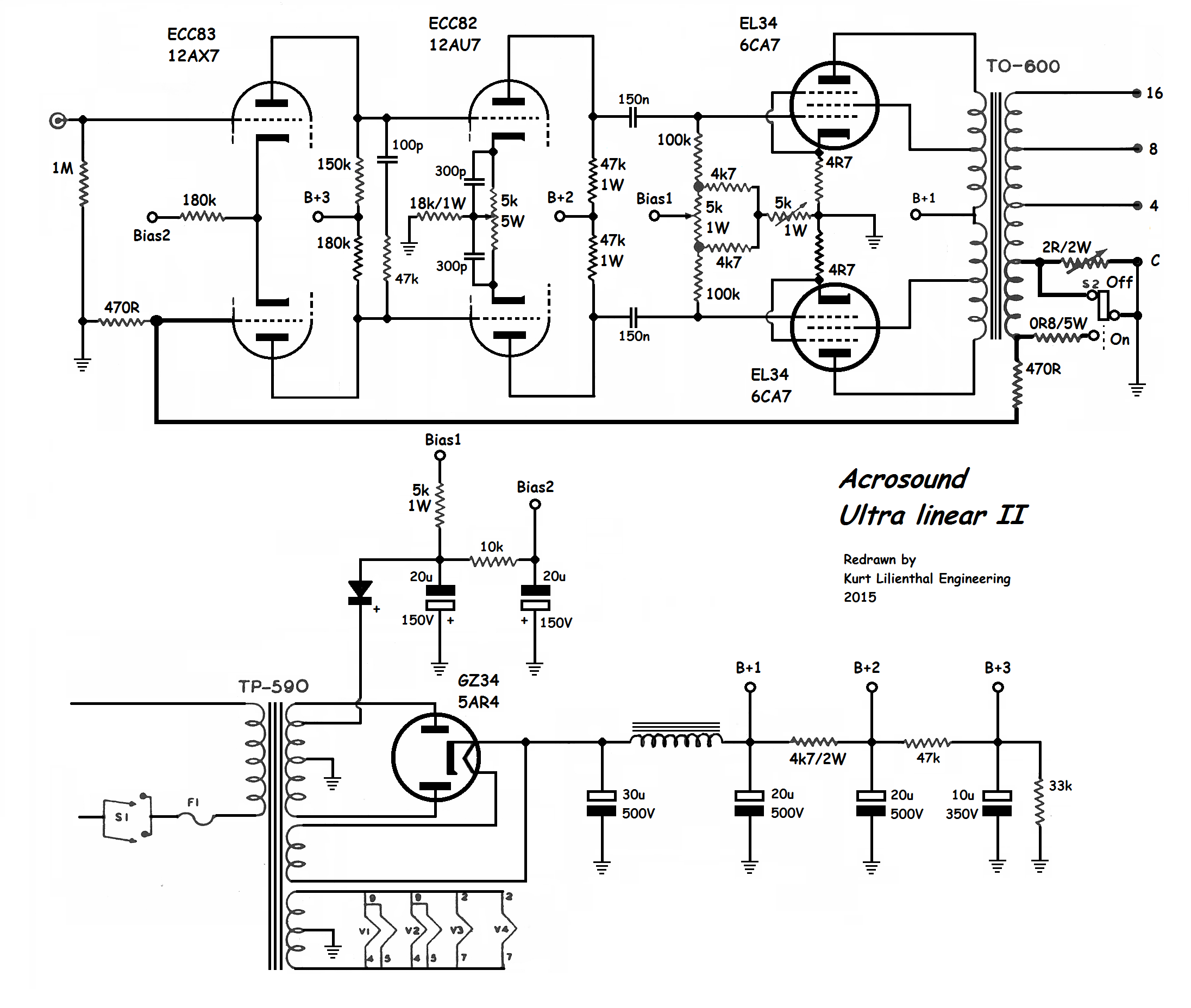
Just to confirm, the Raven and Blackbird do NOT use the Acrosound circuit shown above. The signal path is considerably simpler.
|
Acrosound UL-II schematic. Note the input 12AX7 is direct-coupled to the 12AU7 driver stage, so DC drift from internal 12AX7 mismatch could be a problem.
Technical analysis: The input signal goes to the top half of the 12AX7. The bottom half is connected to the feedback signal, which comes from a dedicated winding on the output transformer. The feedback summation occurs across the paired cathodes of the 12AX7. The plates of the 12AX7 are direct-connected to the grids of the 12AU7 driver.
There is a HF phase-adjust circuit from the 100 pF cap in series with the 47K resistor. This improves the stability of the feedback system. The 12AU7 driver has a 5K 5W current-balancing pot in the cathode circuit, most likely to correct for any DC imbalance of the 12AX7. I suspect the 300p marking of the bypass caps on the 12AU7 is in error. This should be 2 to 10uF, whichever gives the best square-wave response.
Similarly, there is a DC balance pot in the Bias 1 grid circuit of the EL34 output tubes. The 4.7 ohm series resistor in the cathode of each EL34 is there to meter current, which is adjusted by the 5K pot. Although not drawn, there would be test points for each cathode to ensure the correct bias point.
Although not marked as such, this is a fixed-bias output section set up for Class AB (high power) operation. Correct bias setting for each EL34 is essential for long tube life.
|
If all these transformers disgust you, or you want to use local or global feedback, you can re-visit the Acrosound schematic from the late Fifties. Three stages, all differential, each RC-coupled to the next. It can be easily updated with modern current sources on the cathodes, giving precise differential action and almost no even-order distortion. The Acrosound circuit also offers some interesting options with cross-feed feedback between sections.
If you are bold, you can DC-couple some of the stages, but you will need good servo circuits to maintain DC balance as the tubes warm up and then gradually age. The servo circuits also need to be failure-proof, since a runaway servo circuit can destroy the amplifier.
|
In essence, the signal flow is: Complementary Pair of 6SN7 sections -> Signal is re-summed in the transformer -> Complementary Pair of triode-connected KT88 drivers -> Signal is re-summed in the transformer -> Complementary Pair of 300B outputs -> Signal is re-summed in the transformer -> Loudspeaker Output.
To minimize interactions between output section and the rest of the amplifier, there are separate and isolated high-voltage regulators for input + driver section and the output section. The only signal flow, either from the audio path or the power supplies, is from input to output. There are no secondary paths, at least to the 130 dB limit of filter isolation offered by the power supplies.
A few SET amplifiers have a roughly similar signal flow, but only offer a few dB of RC filter stage-to-stage isolation between sections, so there is a signal backflow pathway between sections. Isolated power supplies resolves that problem. In a SET amplifier, 2nd-harmonic distortion builds up from stage to stage, but there can also be unpredictable level-dependent cancellation effects since signal polarity is inverted with each stage.
|
Ralph brings up a very good point about feedback: the underlying theory assumes a distortionless summing point. (The summing point is the comparator input between signal input and the sampled output.) Any distortion introduced at this point of the circuit will be amplified without correction, and there is a real possibility of introducing new, higher-order terms that are not present in the forward path of the physical amplifier. Norman Crowhurst mentions this in passing in his Audio magazine articles in the late Fifties.
Don and I go to some trouble to avoid even local feedback in the Raven and Blackbird ... all cathodes are bypassed in every stage, we do not use the Ultralinear connection in the triode-connected KT88, nor global feedback. Any distortion that is present is the result of first-order effects in the tubes themselves, not anything else. It also mandates selecting tubes that have a minimum of high-order distortion terms in the intended operating range.
This overlaps with the philosophy of some SET amplifier designers, but we prefer to use complementary pairs to cancel most of the distortion without recourse to feedback (local or global). The transformers, if correctly balanced, cancel out most of the distortion before passing the signal to the following stage, thus, each grid-pair is fed a cleaner signal.
This comes in particularly useful for the 300B grids, which can be a difficult nonlinear load for the preceding stage. Unlike RC coupling, when one grid demands current, both phases of the driver pair are available to deliver current to the 300B grid that needs it. This enables seamless and jump-free transition to A2 (positive grid drive) when the signal demands it.
|
@whitestix
When we are treated to a master class in tube design philosophy, freely given, participants clearly appreciate the generous sharing of information by the masters: Don, Lynn and Ralph. It has been a real education for me
Very well put.👍
This thread you initiated has miraculously avoided the all too prevalent trolling and disruptive deterioration. Bravo!!!
Charles
|
Once and always, Charles sets the bar for thoughtful and positive responses to topics on this forum, which in 10 months regarding this thread, have always been very upbeat and positive. When we are treated to a master class in tube design philosophy, freely given, participants clearly appreciate the generous sharing of information by the masters: Don, Lynn and Ralph. It has been a real education for me.
|
@donsachs
It is undoubtedly a different topology than ours and I wish them well. I am sure they will get their version to where they want it to be as we have with ours. They will sound different of course due to the preferences of the designers.
Hi Don, I just want to say that I appreciate your decorum and professionalism. No doubt that the two 300b push pull amplifies will sound differently precisely for the reasons you mentioned. I’ve greatly enjoyed the many insightful and educational contributions from you and Lynn Olsen in this terrific thread.
I wish you and Lynn the best. Also Atma-Sphere with their endeavor as well.
Charles
|
Sounds like @atmasphere is early on their journey with a PP 300b. Certainly far enough along to demonstrate a prototype at a show, much as we did in Seattle last summer.
We started prototyping with DHTs seriously about 20 years ago. Back in the 1990s we built a 300b-based OTL which we showed at CES.
The trick with the CCS is doing a good one. A lot of the circuits that you see on the web leaver performance on the table. We've had CCS circuits in our amps for the last 35 years.
'A lack of solid state coloration' is matter of avoiding the distortion signature that is endemic in so many solid state amps. This has to do with proper design of the feedback loop and a whole lotta loop gain in an amplifier design. The 'solid state' sound is just bad feedback application and is part of why feedback has garnered a bad rep in high end audio.
Feedback has been known to give tube amps a 'solid state' sound too; this is because the feedback signal has been distorted prior to mixing with the audio signal its supposed to correct. Its like having an incorrect map to guide you through town. Norman Crowhurst wrote about this problem nearly 70 years ago but did not suggest a solution, despite it being rather simple. Peter Baxandall 'rediscovered' the same problem in solid state amps about 20 years later but he suggested more feedback, which doesn't solve the problem.
Its only been in the last few years where we've seen self-oscillating class D amps where this problem has been solved pretty consistently. You can do it in class A/AB solid state amps too if you're willing to work out the 3rd or 4th order feedback loops that need to be involved. Most designers just use a resistor which won't cut it...
|
I have done every permutation and combination of ways to build this 300 PP circuit. I originally started with high quality CCS and then went to LC coupling, which sounded more natural and musical to my ear, and then finally went to full transformer coupling. As was stated above, this was impossible with off the shelf iron from even a very well know major European manufacturer. Those ITs rang like a bell at 15K and up. It took several iterations of custom design work in collaboration with Dave Geren at Cinemag to get it right. Dave's easily make it down below 20 Hz and out past 30 KHz with no oscillation and no loading network needed. We all have our taste, and all versions of the amp were wonderful, but there is magic in the final version that simply wasn't there with CCS or LC coupling. A lack of solid state coloration and wonderful tonality and presentation of instruments to my ear. The piano sounds like a piano, not a nice rendition of one.
We are in production after two years of prototyping. Sounds like @atmasphere is early on their journey with a PP 300b. Certainly far enough along to demonstrate a prototype at a show, much as we did in Seattle last summer. It is undoubtedly a different topology than ours and I wish them well. I am sure they will get their version to where they want it to be as we have with ours. They will sound different of course due to the preferences of the designers.
|
Yes, it’s difficult to get people to understand that Class A push-pull is quite a different animal than the much more common Class AB push-pull. I understand the reasons for Class AB ... it’s much more efficient, but Class A working is not the same, since device switching and the saturation region are avoided.
It’s also kind of funny seeing the solid-state fraternity tap-dance around various sliding-bias schemes and the marketing attempts to call them "Class A". Well no, they’re not, since the clever sliding-bias system is always just a little behind the musical content. And genuine (thermal) Class A transistor amps require stupendously large heat-sinks or fan cooling.
I remember all the marketing about "cool-running" transistor amps in the late Sixties. Yes, they ran cool if the Class A region was 1 watt or less, and the rest of the operating envelope was Class B. The A/B switching region was especially offensive with the quasi-complementary amps of the first and second generation. The third generation, in the late Seventies, finally had access to decent quality complementary devices, although dog-slow by modern standards.
Class A working is actually easier with vacuum tubes, since you don’t need a monster heat sink. Solid-state reliability drops pretty fast above 80 deg C, so heat sinks and efficient thermal design are mandatory. By contrast, vacuum tubes operate quite happily at very high temperatures (short of red-plating). If you can accept lower power, it’s easily within reach by altering bias points and the primary impedance of the output transformer.
I agree with you about the merits of single-ended vs Class A push-pull (or balanced). The only indisputable advantage of SE operation is avoiding the zero-crossing region in the output transformer, but this comes at a massive cost in core size and the requirement for a large air gap, which in turn erodes bandwidth. Skillful output transformer design can work around the problems of the zero-crossing region ... this is largely a solved problem.
|
Wow, is that the first Atma-Sphere with an output transformer?
No, nor the first to be shown in public or sold. We make a small 5Watt/channel integrated amplifier that is suitable for desktop, bedroom, headphones or a main system if your speakers have the efficiency.
That one uses EL95s which are a little brother to the 6AQ5, running class A1 ultralinear. The tube is very easy to drive so the voltage amplifier is a differential amplifier using a 12AT7 with a constant current source. The amp can sit on a single sheet of notebook paper with room left over but its built with good parts throughout and an overbuilt power supply. The chassis has its corners welded and ground so it can be polished and chromed. We've been having fun with a variety of finishes and color schemes; blue with black (the transformers be the contrast finish), blue with chrome, black with chrome, chrome with black, grey with red and so on. They are entirely handwired point to point.
It easily keeps up with SETs of the same power; it has a greater amount of usable power owing to greater linearity. It also has wider bandwidth both on the bottom end and the top end (goes out to 100KHz).
This amp is one of the projects we did which aptly demonstrate why SETs are impractical and obsolete.
That's not to say we're not also having fun with SETs. We have a 300b SET project as well. It uses some techniques we use in out OTLs to minimize distortion driving the power tube.
Sounds like the 300B amp is well on track, and I imagine the next version will have current sources in the appropriate positions. I’m curious what your experience with a high-power current source in the output stage turns out to be. It didn’t work for us, but it did work for Allan Wright back when he visited me in the late Nineties.
Constant Current Sources are the key to getting differential amplifiers to perform. A PP output section is often wired as a differential amplifier so a CCS can work really well if output section is class A.
|
Wow, is that the first Atma-Sphere with an output transformer?
Sounds like the 300B amp is well on track, and I imagine the next version will have current sources in the appropriate positions. I’m curious what your experience with a high-power current source in the output stage turns out to be. It didn’t work for us, but it did work for Allan Wright back when he visited me in the late Nineties.
|
Ralph, I see you introduced a PP 300B amplifier at one of the recent hifi shows. How do you think it compares to your Class D amplifier, in subjective terms?
The prototypes at the show sound very similar to our class D amps; the big difference is the bass- the prototypes roll off at a higher frequency, and owing to no feedback and the OPT design don't throttle back their power when dealing with higher impedances, such as seen in the CALs at the show, which are bass reflex. So there was a bit of extra energy in the double impedance peak of the speaker. Its fun, but not correct.
Essentially that OPT loads the tubes at their power peak rather than a bit higher where the amp would have had a better chance at being more like a Voltage source. If the next iteration of the OPTs had been available, the bass would have been a lot more like the OTLs but ultimately lacking the extension that up until now has been something that OTLs do better than any other kind of tube amplifier.
The class D has the same relaxed mids and highs but is a little more transparent- its easier to hear what's going on in the rear of the sound stage if you have a 2-mic recording.
I think we can do better with the 300bs by using some of the tech we use in our OTLs. So the next PP version of the amp will be quite a bit different- with LF bandwidth similar to our OTLs with no sacrifice in high frequency bandwidth.
|
That is the first thing you notice when you hear our 300b PP. The bass is amazing. It is not over emphasized at all, but if there is bass energy on the recording you hear it all. Most importantly, it is the quality of the bass, not the quantity. When I built the prototype I had never heard anything like it. The resonance in the body of instruments, the attack and decay of bass notes. Then we spent over two years improving the amps by eliminating cap coupling, improving power supply designs, working with Dave Geren through several iterations of custom interstage transformers, moving to Monolith output transformers, etc... Now the bass is otherworldly. So I can imagine a well designed PP 300b is going to have those qualities with a good field coil speaker and make people take notice.
|
@lynn_olson
“Ralph, I see you introduced a PP 300B amplifier at one of the recent hifi shows. How do you think it compares to your Class D amplifier, in subjective terms? Since you designed both, you're the best qualified to assess the differences.”
There are a few of us curious audio geeks interested in learning more. John Wolf of Classic Audio Loudspeakers used them with his field coil speakers and he said that the bass was incredible. Perhaps time to ditch the Novacrons he uses a lot for the new 300.
|
@donsachs
I tried to post a new link but it gets blocked. You have to Google Soundstage SOUTHWEST Texas audio show. Not sure why the link gets blocked, weird. Use atmaspehere 300b prototype in search string.
|
Ralph, I see you introduced a PP 300B amplifier at one of the recent hifi shows. How do you think it compares to your Class D amplifier, in subjective terms? Since you designed both, you're the best qualified to assess the differences.
|
One of the nice things about working with Cinemag is their custom design service. This gets us away from the many limitations of standard off-the-shelf transformers from other vendors. We specify source impedance, the range of loads (including capacitance), DC current flow, and expected DC imbalance. They show us what their computer model tells them, we test the physical prototype, see how it works on the bench and in-circuit, and go back and forth a few times until everyone is happy. Off the shelf, it's take it or leave it.
This is what made both the Raven and Blackbird possible. I didn't think a transformer using the 6SN7 in balanced mode could be realized because of the quite high impedances involved. To my surprise, Cinemag showed me otherwise ... very clean square waves at 10 kHz with minimal overshoot. This is not an off-the-shelf part ... it's been designed for us.
When we say the Raven and Blackbird use custom parts we aren't joking. Without them, they aren't practical. We use standard tube types because we want our customers to enjoy them for a long time, and we expect the 6SN7, KT88/6550, and 300B to be around a long time. Under the chassis, though, we use custom parts for critical functions.
|
The Raven is not very sensitive to loads. In practice, power amps range from 10K (typical solid-state) to as high as 470K for a handful of vintage tube amps. Most modern tube amps are 100K. Plus whatever cable capacitance is there, along with the Miller capacitance of the input section of the power amp. So 100 to 400 pF is typical. The range of loads is predictable and well known.
What dominates the transformer performance is the source impedance, not the load. The source impedance from the preamp tube is much lower than the load, so it heavily dominates the transformer performance. Transformers don’t much care where the low impedance is, primary or secondary, so long as it is there.
Transformers are aptly named as they transform impedance. They do not isolate impedance. If the source impedance is low that will change the correct loading on the output (as opposed to a high source impedance), which will be found to be exactly one value. Above that value the transformer will ring; below that value it will roll off highs.
This phenomena is well known and is why Jensen Transformers specifies the loading to be used with their SUTs depending on what cartridge is used with them.
If the load is too high impedance, the inter-winding capacitance will come into play as well, causing the FR to no longer be flat, and in extreme cases the transformer may fail to express its turns ratio. The proper termination will yield the widest bandwidth out of the transformer.
This why in the old days when balanced lines were used, the termination standard was always 600 Ohms so the designer would have a pretty good idea of what to shoot for.
A rheostat, placed across the output (between pins 2 and 3) can be used to load the transformer for optimal operation. Or the transformer can be designed for 600 Ohms with a termination switch using a 600 Ohm resistor built into the equipment (this is how Ampex solved this issue on their 351 tape electronics). That way any higher impedance load such as 10K or 100K is negligible and would not affect the transformer performance. The latter approach is why we did with our P-2 balanced line preamp 30 years ago.
|
@audioquest4life
I did not make it to the room you mentioned above. I was quite busy running our room with Spatial Audio Lab and only made it to about half the rooms at the show. The link you posted did not work. Can you check and repost it?
|
Of course, it is tempting to design a special-purpose headphone amp. I own HifiMan HE1000 Stealth (V3) planar headphones myself, and I use a modest all-in-one DAC/headphone amp to power them.
But ... the headphone amp market is quite crowded, and is dominated by Chinese products selling from $200 to $1600. On the domestic front, Geshelli is cleaning up making AKM-based DACs and Sparkos discrete-opamp headphone amps at entry-level pricing. As far as I can tell, headphones, and headphone amps, is the most competitive sector of the audio market right now.
So even if we spent several months to a year on a special headphone amp, I’m not sure we’d sell many. Something to think about, though.
|
In terms of load abuse, plugging planar headphones (20 ohm to 32 ohms) into the Raven preamp will definitely load down the preamp and is not recommended. No harm will result, but the preamp will slide over into Class AB operation and distortion will rise to higher levels. Headphones with impedances of 300 ohms or higher (most dynamics) are fine.
We may design a future project that can accommodate planar headphones, but these require a genuine 1 to 2 watt Class A power amplifier, which is outside the scope of a preamplifier intended to drive power amplifiers. In other words, a tiny but very high quality power amp with extremely quiet power supplies. Designing (good) amplifiers for planar headphones is not as simple as it appears at first glance.
|
The Raven is not very sensitive to loads. In practice, power amps range from 10K (typical solid-state) to as high as 470K for a handful of vintage tube amps. Most modern tube amps are 100K. Plus whatever cable capacitance is there, along with the Miller capacitance of the input section of the power amp. So 100 to 400 pF is typical. The range of loads is predictable and well known.
What dominates the transformer performance is the source impedance, not the load. The source impedance from the preamp tube is much lower than the load, so it heavily dominates the transformer performance. Transformers don’t much care where the low impedance is, primary or secondary, so long as it is there.
The hard transformers to design are the interstage transformers, since they are driving nothing more than a grid (without grid resistors). So the load is effectively nothing more than the Miller capacitance, which is fortunately a known quantity and can be designed around. Similarly, the source impedance is also known, since it is the plate impedance of the preceding tube. We use transformers that are purpose designed for the impedances and the power range they will be exposed to in-circuit. (Not off-the-shelf general-purpose transformers.) One nice thing is our transformer designer has access to modern magnetic simulation tools that were not available back in the Thirties and the Fifties.
|
Pin 1 is shield and grounded to chassis, pin 2 is XLR + phase and pin 3 is XLR - phase. It will drive any power amp with XLR connections, and will happily drive a 10K amp input impedance.
@donsachs How do you deal with the variable loads which the preamp will be driving? With no feedback, the transformer can ring or express the inter-winding capacitance if its not loaded correctly.
|
We just did the sw audio fest in Dallas using the original version and we had one of the top rooms at the show. It really isn't a big change.
|
@fthompson251
Hi. It is a very subtle change that I find inaudible, but on paper it is slightly better. The xlr inputs now go directly to the Attenuator and the rca go through a 1:1 transformer to convert to xlr. The previous version ran all inputs through the 1:1 transformer. Honestly, the Cinemag 1:1 transformer is so good that it has something like .25 degree phase shift at 20 Hz. You cannot see it on the oscilloscope and it is sonically transparent. So running the xlr through it was not an issue, but I figured out how to go direct in for the xlr. Again, I changed my preamp and I really cannot tell much difference on the xlr between input transformer coupled and direct. I doubt I could reliably tell in a blind test. The transformer is that good. So if you are using predominantly rca inputs to the preamp there is no change. If you are using the xlr inputs, then there is a change on paper, but you would be hard pressed to hear the difference.
|
@lynn_olson @donsachs I’ve been in touch with David Whitt about the pre amp, he said they are shipping the first build cycle in May of this year. He also stated that there is a 6 week build cycle. It seems you are still making changes to it at the moment, at least from what I gathered in this thread? Would it be wise to hold off a bit for a couple months until you determine the final product? I am not in a hurry, but searching for my end game preamp and want te best version of it.
|
|
@fthompson251
I understand, retubing 8 300bs can certainly add up. I hope your VAC REN 70/70 finds a wonderful new home. I can also understand the desire to simplify one’s audio system.
Charles
|
@charles1dad Yes, it was a very tough decision but I cannot lift the damn thing anymore and re tubing it is nearly $2000. I want to simplify my retired life a bit. I just picked it up from VAC and it is fresh as a daisy for the new owner. New tubes with about 100 hours on them.
|
@fthompson251
Is the Coda amplifier replacing your iconic VAC Renaissance 70/70. amplifier? I have no doubt that the Raven preamplifier would work marvelously with either.
Charles
|