Dedicated power circuits


I’m having some electrical work done including a whole house

generator, surge suppressor, and a new panel box. I am also going to have two dedicated power lines run for my stereo. I’ve read a lot on here about how this is a really nice upgrade and would greatly appreciate any advice to help me along on my project. Right now the plan is two 20 amp circuits with 10 gauge wire. One for my amp and one for my preamp and sources. My equipment is a McIntosh MC 452, a C47 right now but a C22 in the future, Rega P8, Rose hifi 150b,  McIntosh MR 74 tuner and Aerial 7t speakers. I’m also replacing my panel box with a new one. It’s a brand from a company that’s out of business and the quality and safety is suspect plus there are no new breakers available.


So starting with the breakers, then the wire and finally the receptacles what should I be looking for? The electrician that just left here is planning on the new panel being a Cutler Hammer brand. Any help would be greatly appreciated.


128x128gphill

Recommendations for power receptacles from a previous post of mine

"I do HIGHLY suggest quality recepticles (not just hospital grade). Furutech GTX-D is what I am running right now, butt also had great sound from Oyaide R1 (NOT the SWO series), Cardas, and PS Audio...though the PS Audio is the worst of the lot, but still an improvement."

I ‘ve 3 same lenght dedicated lines.

Easy to install, more if you’re - congrats- building something new.

A Doepke 3P circuit breaker and protection switch with an N common pole and 3?line Oyaide Tunami V2 cable 

-1 feeds the Atmasphere MA-1 AMP

-1 feeding Soundlab U-545 SPEAKERS

-1 feeding sources

The result is wonderful, the punch and crystal sound, speed and image is making me enjoy music.

Hope this can help. I don’t know how to insert some images, sorry


I installed a sub panel with 6/3 w/ground to the room with a 65 amp breaker in the main panel. Then I pulled off a 240v-20a for the big amps and a couple of 120v 20a circuits for the wall outlets, 120v 15a for lights. That way, instantaneous power draw could be very high with nearly no drop in voltage. Future proofing. 

@8th-note,

.


~ ~

Is this what you are looking to buy? You do know it is 120/240V? Best practices is to feed audio equipment, (that is connected together by wire ICs), is to feed the 120V equipment from branch circuit breakers fed from same Line. All from Line 1 or all from Line 2. Not from both.


You mentioned Michael Fremer’s new electrical service. All his audio equipment is fed from one 120V Line. I have no idea how big his total load is though. Just a guess a lot more than yours.

.


~ ~

I watched the video again today and picked up a few things I missed the first two previous times. I believe there are a few things worth noting.

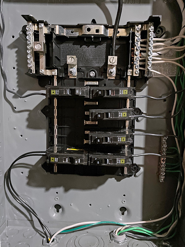
Near the end of the video Fremer shows the new sub panel for his audio room. It is fed 120V only. *(1)* Electrical Inspector did make the electrician install the other 120V hot conductor. It will not be used though. I think it was just an AHJ Inspector thing. I couldn’t find anything in the NEC that requires it.)

Note the 120V feeder for the sub panel is installed in PVC conduit. All the branch circuit wiring is installed in non metallic flexible conduit.

Example, non metallic flexible conduit:

1/2-in x 25-ft Ultratite Non-metallic Schedule 80 Liquid-tight Conduit

From what I could see the outlet boxes are also non ferrous as well as the outlet cover plates. I did see something I didn’t agree with though. Two dedicated circuits for the two mono amps were pulled in the same raceway, conduit. That doesn’t follow best practices. I did notice though the 120V Hot, Neutral, and Ground branch circuit wiring used for each 120V circuit was apparently tightly twisted together. That would be a whole lot better than if single conductors for both dedicated circuits were all pulled loosely together in the conduit. That definitely is a no, no. A sure way to induce an AC voltage onto the equipment grounding conductors and cause ground loop hum.

Image of audio room sub panel, front cover removed. Note the two 120V dedicated circuits bottom right side of panel in the flex conduit connector.

.

1121acorny.3


.

/ / / /


Not to bad mouth the electrician. He may have had his reasons... I did notice a few things on the installation of the new electrical service I didn’t care for.

The use of a rigid no-thread coupling on the Mast rigid Conduit. (Yeah it meets code. But...)

The use of the offset nipple into the top of the meter socket enclosure hub. Not pretty...

And I found myself scratching my head why the electrician used PVC conduit nipple from the bottom of the meter socket enclosure to the Myers Hub on the main service equipment panel. A galvanized rigid nipple would have looked a lot better, jmho... As well as electrically bonding the two metal enclosures together.


/ / /


*(1)* Electrical Inspector did make the electrician install the other 120V hot conductor.

I have a friend in Texas that has a 15KVA 240V to 120V single phase pad mount outdoors isolation transformer strictly for feeding his two channel audio room equipment. The electrician only installed one, Hot, neutral, and ground, conductor to feed the 120V only electrical panel. The electrical inspector made the electrician add the additional spare conductor for the other hot Line, ( for future), not used, not connected.

.

@lowrider57 Wrote:

@ditusa

Please explain why MC Galvanized Steel Metal Clad Cable. A metal conduit is not required to meet code in this situation. And cost will be higher than Romex 10/2.

The MC Galvanized Steel Metal Clad cable provides better shielding versus 10/2 Romex, in my opinion the benefits outweigh the extra cost of the MC which is minimal. The advantage of MC cable is low line noise and reduced antenna effect on AC dedicated branch circuits feeding your audio equipment. Also, I prefer to use metal boxes with MC cable, not plastic, they both meet code but if shielding is not important then the 10/2 Romex with plastic boxes will be more then adequate. I just try to get the most out of my audio system as I can with minimal cost. 😎 See MC cable below: Hope that helps

FWIW: Another reason for multiple circuits besides dedicated power see my previous post below:

ditusa’s avatar

ditusa

1,073 posts


@jea48Wrote:

Probably the biggest reason for installing more than one Dedicated Branch Circuit is to decouple the power supplies of audio equipment from one another. Example digital source(s) equipment from analog equipment.

I agree!

That was one of the reasons I ran four 60’ runs of galvanized steel armored MC cable 10AWG. That’s four true dedicated branch circuits, one for each mono block amp, one for analog and one for digital. It helps to reduce noise on the AC lines, by reducing the amount of transformers and power supplies on each circuit. Also, the MC helps to reduce hashing noise EMI, and electric fields, on the dedicated branch circuits feeding your audio equipment. You don’t realize how much hashing noise is on the AC lines, until it’s reduced. No ground loop hum. No noise. System is dead quiet with ear against speaker horn, I have tube and SS amps. (The efficiency of my speakers is 2.7% sensitivity 96dB). 😎

Mike